


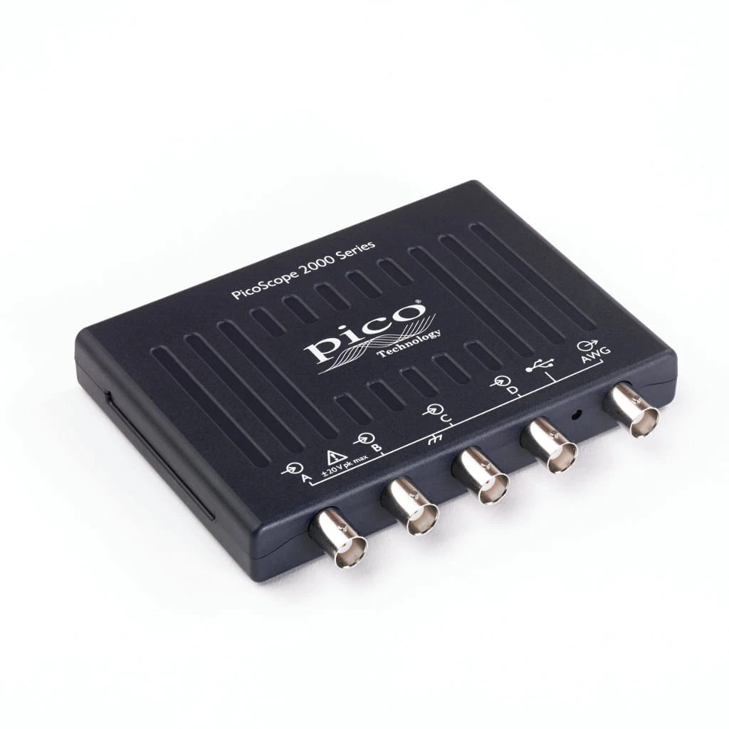
Oscyloskop PicoScope 2405A
PicoScope 2405A to kompaktowy oscyloskop USB z konfiguracją 4 analogowe, pasmem 25 MHz i pamięcią 48 kS. Ten model jest szczególnie dobry dla użytkownika, którego priorytetem jest najprostszy wybór, gdy ważne są cztery kanały analogowe w bardzo kompaktowej obudowie.
Kod produktu: PQ015
Opis produktu
PicoScope 2405A to model dla użytkownika, który potrzebuje laboratorium dydaktyczne, serwis lub automatyk, który chce jednocześnie widzieć kilka wolniejszych sygnałów analogowych. W obrębie rodziny 2000 jego główną rolą jest najprostszy wybór, gdy ważne są cztery kanały analogowe w bardzo kompaktowej obudowie.
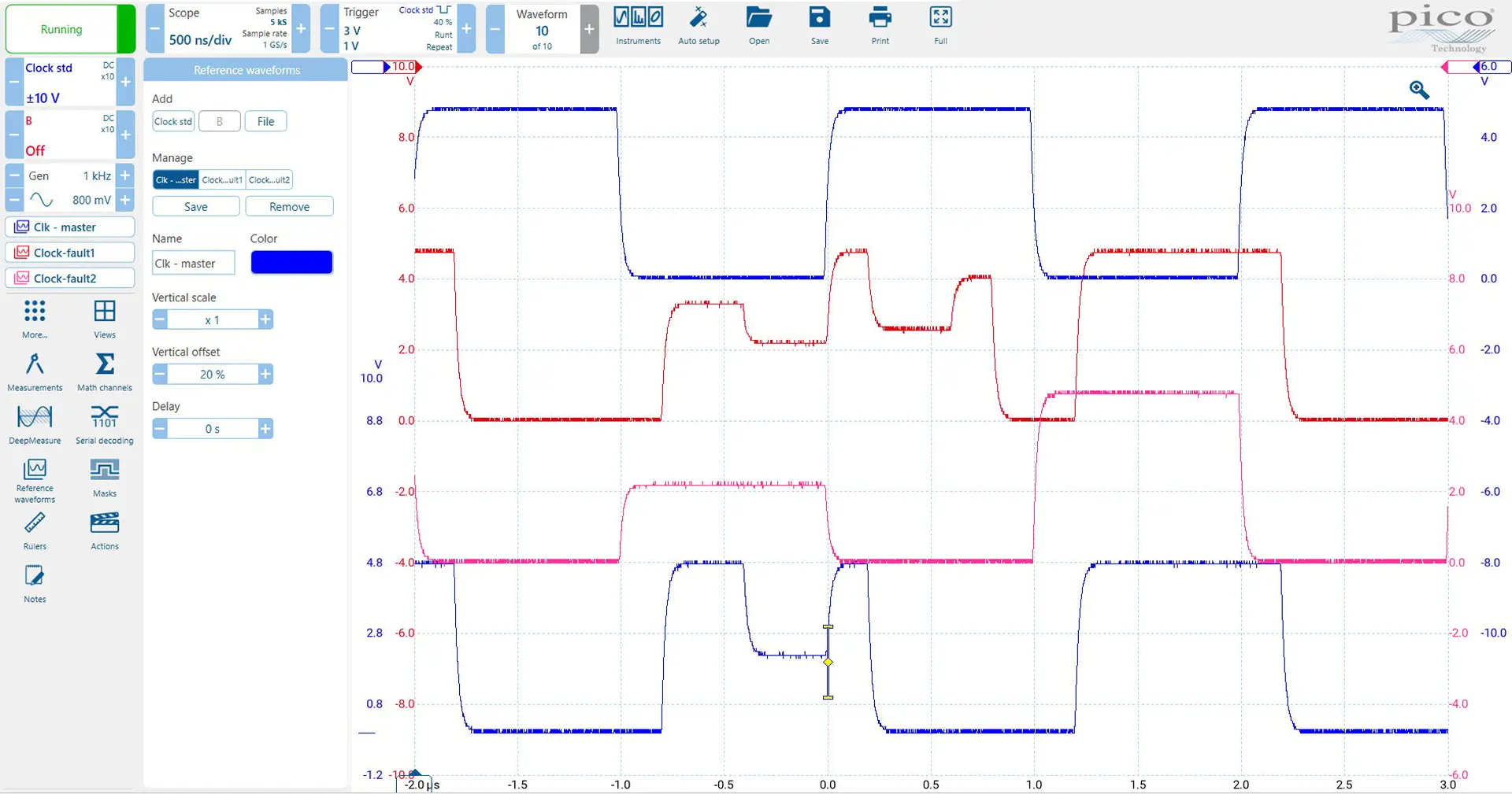
Cztery wejścia analogowe są przydatne wtedy, gdy problemu nie da się zrozumieć patrząc tylko na jeden przebieg. Możesz porównać kilka punktów pomiarowych jednocześnie i łatwiej ocenić zależności czasowe między nimi.
Do jakich zastosowań sprawdzi się PicoScope 2405A?
Ten model został opisany pod kątem praktycznego scenariusza pracy, a nie tylko tabeli parametrów. Najlepiej sprawdzi się w sytuacjach, w których potrzebujesz szybkiego pomiaru, zapisu danych i wygodnej analizy na komputerze.
- porównanie kilku napięć zasilających
- obserwacja czujnika, sterowania i odpowiedzi układu jednocześnie
- zajęcia laboratoryjne wymagające czterech wejść
- diagnostyka prostych układów automatyki i sterowania
Co wyróżnia ten model w serii 2000?
Cztery kanały analogowe pozwalają analizować układ bez ciągłego przepinania sond. W praktyce można jednocześnie obserwować wejście, wyjście, sygnał sterujący i napięcie zasilania, co znacznie skraca diagnostykę złożonych układów.
PicoScope 2405A oferuje konfigurację 4 analogowe, pasmo 25 MHz, próbkowanie do 500 MS/s i pamięć 48 kS. Dzięki generatorowi funkcyjnemu/AWG można nie tylko obserwować sygnał, ale również pobudzać badany układ i od razu analizować jego odpowiedź.
Kompletny ekosystem oprogramowania Pico Technology
Oscyloskop USB, rejestrator danych i środowisko do automatyzacji
Kupując PicoScope z serii 2000 otrzymujesz nie tylko kompaktowy oscyloskop USB, ale również środowisko pracy oparte na oprogramowaniu PicoScope 7 T&M, PicoLog 6 i PicoSDK. Dzięki temu to samo urządzenie może służyć do bieżącej obserwacji przebiegów, długoterminowej rejestracji sygnałów oraz integracji z własnymi aplikacjami pomiarowymi.
PicoScope 7 T&M umożliwia pracę z przebiegami, pomiarami automatycznymi, analizą FFT, dekodowaniem magistral, maskami i zapisem konfiguracji. PicoLog 6 pozwala wykorzystać oscyloskop jako prosty rejestrator danych, a PicoSDK jest przeznaczony do automatyzacji testów i budowy własnych stanowisk pomiarowych.
Programy można pobrać bezpłatnie i uruchomić w trybie demonstracyjnym bez podłączonego urządzenia. To dobry sposób, aby przed zakupem sprawdzić interfejs, przykładowe przebiegi i sposób pracy z danymi.
PicoScope 7 T&M i PicoLog 6 można uruchomić w trybie demonstracyjnym bez podłączonego oscyloskopu.
Najważniejsze parametry techniczne
| Parametr | PicoScope 2405A |
|---|---|
| Liczba kanałów | 4 analogowe |
| Pasmo analogowe | 25 MHz |
| Maksymalna częstotliwość próbkowania | 500 MS/s |
| Pamięć akwizycji | 48 kS |
| Generator | generator funkcyjny / AWG |
| Typ modelu | oscyloskop analogowy |
Pełną specyfikację należy zawsze zweryfikować z kartą katalogową producenta oraz wariantem handlowym oferowanym w sklepie.
Kiedy wybrać model wyższy lub niższy?
Wybierz PicoScope 2405A, jeżeli jego pasmo 25 MHz, konfiguracja 4 analogowe i pamięć 48 kS odpowiadają Twojemu typowemu scenariuszowi pracy. Rozważ model wyższy: 2406B, jeżeli potrzebujesz 50 MHz i głębokiej pamięci. Rozważ model niższy: 2205A, jeżeli wystarczą dwa kanały analogowe i niższy koszt jest ważniejszy niż liczba wejść.
Co znajduje się w zestawie?
W zestawie otrzymujesz oscyloskop PicoScope oraz dostęp do oprogramowania PicoScope 7 T&M, PicoLog 6 i PicoSDK. W zależności od konkretnego wariantu sprzedażowego produkt może być oferowany z sondami lub bez sond, dlatego przed zakupem warto sprawdzić zawartość zestawu na karcie produktu.
Potrzebujesz pomocy w wyborze?
Nie masz pewności, który PicoScope 2000 wybrać? Opisz sygnały, które chcesz mierzyć, liczbę wymaganych kanałów i to, czy potrzebujesz analizy cyfrowej MSO. Dobierzemy model do konkretnego zastosowania.
Specyfikacja techniczna
| PicoScope model | |||||||
|---|---|---|---|---|---|---|---|
| Bandwidth (−3 dB) | 10 MHz | 25 MHz | 50 MHz | 70 MHz | 100 MHz | ||
| 2-channel | 2204A | 2205A | 2206B | 2207B | 2208B | ||
| 4-channel | 2405A | 2406B | 2407B | 2408B | |||
| 2-channel MSO | 2205A MSO | 2206B MSO | 2207B MSO | 2208B MSO | |||
| Model number | 2204A | 2205A | 2405A 2205A MSO |
2206B | 2406B 2206B MSO |
2207B 2407B 2207B MSO |
2208B 2408B 2208B MSO |
|---|---|---|---|---|---|---|---|
| Vertical (analog channels) | |||||||
| Bandwidth (−3 dB) | 10 MHz | 25 MHz | 50 MHz | 70 MHz | 100 MHz | ||
| Rise time (calculated) | 35 ns | 14 ns | 7 ns | 5 ns | 3.5 ns | ||
| Vertical resolution | 8 bits | ||||||
| Enhanced vertical resolution Resolution enhancement can provide up to 4 bits of additional resolution (improving the ability to see small changes in the waveform). Resolution enhancement provides similar results to waveform averaging, but can be done with single shot-signals. Read more... |
Up to 12 bits | ||||||
| Input ranges | ±50 mV, ±100 mV, ±200 mV, ±500 mV, ±1 V, ±2 V, ±5 V, ±10 V, ±20 V | ±20 mV, ±50 mV, ±100 mV, ±200 mV, ±500 mV, ±1 V, ±2 V, ±5 V, ±10 V, ±20 V | |||||
| Input sensitivity | 10 mV/div to 4 V/div | 4 mV/div to 4 V/div | |||||
| Input coupling | AC/DC | ||||||
| Input connector | BNC (f) | ||||||
| Input characteristics | 1 MΩ ± 1% || 15 pF ± 2 pF | 1 MΩ ± 1% || 16 pF ± 1 pF | |||||
| Analog offset range Vertical position adjustment. Read more... |
None | ±250 mV (20 mV to 200 mV ranges) ±2.5 V (500 mV to 2 V ranges) ±20 V (5 V to 20 V ranges) |
|||||
| Analog offset accuracy Can be improved by using the "zero offset" function in the PicoScope software. | N/A | ±1% of offset setting, in addition to basic DC accuracy | |||||
| DC accuracy | ±3% of full scale ± 200 μV | ||||||
| Overvoltage protection | ±100 V (DC + AC peak) | ||||||
| Vertical (digital channels, MSO models only) | |
|---|---|
| Input channels | 16 channels (two ports of eight channels each) |
| Input connectors | 2.54 mm pitch, 10 × 2-way connector |
| Maximum input frequency | 100 MHz (200 Mb/s) |
| Minimum detectable pulse width | 5 ns |
| Input characteristics | 200 kΩ ± 2% || 8 pF ± 2 pF |
| Input dynamic range | ±20 V |
| Digital threshold range | ±5 V |
| Overvoltage protection | ±50 V |
| Threshold grouping | Two independent threshold controls Port 0: D0 to D7; Port 1: D8 to D15 |
| Threshold range | ±5 V |
| Port threshold accuracy | ±350 mV (inclusive of hysteresis) |
| Hysteresis | < ±250 mV |
| Minimum input voltage swing | 500 mV pk-pk |
| Channel-to-channel skew | 2 ns, typical |
| Minimum input slew rate | 10 V/μs |
| Model number | 2204A | 2205A | 2405A 2205A MSO |
2206B | 2406B 2206B MSO |
2207B 2407B 2207B MSO |
2208B 2408B 2208B MSO |
|---|---|---|---|---|---|---|---|
| Horizontal | |||||||
| Maximum sampling rate | |||||||
| Real-time (block mode) The maximum sampling rate is shared between active channels. On MSO models, each group of eight inputs counts as a channel. The maximum sampling rate on MSO digital channels is 500 MS/s. | 100 MS/s | 200 MS/s | 500 MS/s | 1 GS/s | |||
| Equivalent sampling (ETS mode) Equivalent Time Sampling (ETS) is a way of increasing the effective sampling rate of a scope. It builds a picture of a repetitive signal by overlaying successive captures. In this way, PicoScope is able to accurately capture signals even with frequencies higher than the maximum real-time sampling rate. Read more... |
2 G/s | 4 GS/s | 5 GS/s | 10 GS/s | |||
| USB streaming, PicoScope 7 In USB streaming mode, data is passed directly to the PC without being buffered in the PicoScope's internal memory. Streaming mode allows long periods of slower data collection, which is ideal for chart recording and data logging applications. Read more... |
1 MS/s | 9.6 MS/s | |||||
| USB streaming, PicoSDK | 1 MS/s | 5 MS/s | 31 MS/s | ||||
| Shortest timebase | 10 ns/div | 5 ns/div | 2 ns/div | 1 ns/div | |||
| Longest timebase | 5000 s/div (approx. 14 hours per waveform) | ||||||
| Buffer memory Buffer memory is shared between active channels. On MSO models, each group of eight inputs counts as a channel. | |||||||
| Block mode In block mode, the oscilloscope captures data, stores it in the internal memory, then processes and transfers it to the display or PC before capturing the next block. Block capture mode lets you use the fastest sampling rates because it minimizes communications overhead. Read more... |
8 kS | 16 kS | 48 kS | 32 MS | 64 MS | 128 MS | |
| USB streaming mode, PicoScope 7 In USB streaming mode, data is passed directly to the PC without being buffered in the PicoScope's internal memory. Streaming mode allows long periods of slower data collection, which is ideal for chart recording and data logging applications. Read more... |
100 MS, shared between active channels | ||||||
| USB streaming mode, PicoSDK | Limited only by PC | ||||||
| Waveform buffers, PicoScope 7 PicoScope can adjust the number of chunks the memory is split into, letting you choose between longer recordings per trigger point, or more triggers captured. Recorded waveforms are useful for debugging. Read more... |
10 000 | 40 000 | |||||
| Segmented memory buffers, PicoScope 7 On oscilloscopes with a small amount of on-board memory, the waveform buffer is stored on the PC, which needs more communication. With more memory, rapid trigger mode is available. Rapid triggers store data in segmented memory buffers, which must be stored on the oscilloscope. Read more... |
N/A | 96 | 40 000 | ||||
| Segmented memory buffers, PicoSDK | N/A | 96 | 128 000 | 256 000 | 500 000 | ||
| Maximum waveforms per second The waveform update rate is different to the sample rate. The waveform update rate tells you how quickly an oscilloscope can capture and process entire waveforms, taking into account dead time between captures. Read more... |
2000 | 80 000 | |||||
| Initial timebase accuracy | ±100 ppm | ±50 ppm | |||||
| Timebase drift | ±5 ppm per year | ||||||
| Sample jitter | 30 ps RMS, typical | 20 ps RMS, typical | 3 ps RMS, typical | ||||
| ADC sampling | Simultaneous | ||||||
| Model number | 2204A | 2205A | 2405A 2205A MSO |
2206B | 2406B 2206B MSO |
2207B 2407B 2207B MSO |
2208B 2408B 2208B MSO |
|---|---|---|---|---|---|---|---|
| Dynamic performance (typical) | |||||||
| Crosstalk (full bandwidth, equal ranges) | Better than 200:1 | Better than 300:1 | |||||
| Harmonic distortion | < −50 dB at 100 kHz, full scale input | ||||||
| SFDR Spurious free dynamic range (100 kHz, full-scale input) | > 52 dB | ±20 mV range: > 44 dB ±50 mV range and higher: > 52 dB |
|||||
| Noise | < 150 μV RMS (±50 mV range) | < 220 μV RMS (±50 mV range) | < 300 μV RMS (±50 mV range) | ||||
| Bandwidth flatness | (+0.3 dB, −3 dB) from DC to full bandwidth | ||||||
| Triggering | ||
|---|---|---|
| Trigger sources | ChA-D, MSO channels (if available) | |
| Trigger modes | None, auto, repeat, single, rapid (segmented memory) Rapid triggers are not available on 2204A and 2205A models due to insufficient memory. Read more... |
|
| Advanced triggers | Edge (rising, falling, rising-or-falling), window (entering, exiting, entering-or-exiting), pulse width (positive, negative or either pulse), window pulse width (time inside, time outside or either), level dropout (high, low or either), window dropout (inside, outside or either), interval, logic, runt (positive or negative) , Runt pulse triggers are not available on the 2204A and 2205A models. transition time (rise, fall) Transition time triggers are available on B models only. Logic trigger capabilities: AND or OR function of any number of trigger sources (analog channels, MSO ports) NAND/NOR/XOR/XNOR of any trigger sources User-defined Boolean function of any trigger sources (PicoSDK only) |
|
| ETS triggers | Rising or falling edge (Ch A - all models. Ch B - 2204A and 2205A only) | |
| Trigger sensitivity (real-time) | Digital triggering provides 1 LSB accuracy up to full bandwidth | |
| Trigger sensitivity (ETS) | 10 mV pk-pk, typical, at full bandwidth | |
| Maximum pre-trigger capture | 100% of capture size | |
| Maximum post-trigger delay | 4 ×10⁹ samples | |
| Trigger rearm time | PC-dependent (2204A, 2205A) < 2 μs on fastest timebase (2405A, 2205A MSO, 2206B) < 1 μs on fastest timebase (all other models) |
|
| Segmented memory buffers | See Horizontal specifications above | |
| Maximum trigger rate | PC-dependent (2204A, 2205A) 96 waveforms in a 192 μs burst, at 500 MS/s sampling rate, typical (2405A, 2205A MSO) 10 000 waveforms in a 12 ms burst, at 500 MS/s sampling rate, typical (all B models) |
|
| Model number | 2204A | 2205A | 2405A 2205A MSO |
2206B | 2406B 2206B MSO |
2207B 2407B 2207B MSO |
2208B 2408B 2208B MSO |
|---|---|---|---|---|---|---|---|
| Function generator PicoScopes are equipped with a signal generator. The output frequency, voltage and shape can be configured. It is ideal for R&D but also validation and repair. Read more... |
|||||||
| Standard output signals | Sine, square, triangle, DC voltage, ramp, sinc, Gaussian, half-sine | ||||||
| Pseudorandom output signals | None | White noise, PRBS | |||||
| Output frequency | DC, 0.1 Hz to 100 kHz | DC, 0.03 Hz to 1 MHz | |||||
| Sweep modes | Up, down, up/down, down/up. With selectable start/stop frequencies and increments | ||||||
| Triggering | None | Free-run or up to 1 × 10⁹ waveform cycles or frequency sweeps. Triggered from scope trigger or manually | |||||
| Output frequency accuracy | Oscilloscope timebase accuracy ± output frequency resolution | ||||||
| Output frequency resolution | < 0.02 Hz | < 0.01 Hz | |||||
| Output voltage range | ±2 V | ||||||
| Output adjustments | Any amplitude and offset within ±2 V range | ||||||
| Amplitude flatness (typical) | < 1 dB to 100 kHz | < 0.5 dB to 1 MHz | |||||
| DC accuracy | ±1% of full scale | ||||||
| SFDR (typical) | > 55 dB at 1 kHz full-scale sine wave | > 60 dB at 10 kHz full-scale sine wave | |||||
| Output characteristics | Front panel BNC, 600 Ω output impedance | ||||||
| Overvoltage protection | ±20 V | ||||||
| Model number | 2204A | 2205A | 2405A 2205A MSO |
2206B | 2406B 2206B MSO |
2207B 2407B 2207B MSO |
2208B 2408B 2208B MSO |
|---|---|---|---|---|---|---|---|
| Arbitrary waveform generator The arbitrary waveform generator uses the same output as the function generator. While the function generator uses predefined signals such as sine, square or PRBS, an arbitrary waveform generator can produce any waveform and supports import from .CSV files or live traces. Read more... |
|||||||
| Update rate | 1.548 MHz | 20 MHz | |||||
| Buffer size | 4 kS | 8 kS | 32 kS | ||||
| Resolution | 12 bits | ||||||
| Bandwidth | > 100 kHz | > 1 MHz | |||||
| Rise time | < 2 μs | < 120 ns | |||||
| Spectrum analyzer The spectrum view plots amplitude vs. frequency and is ideal for finding noise, crosstalk or distortion. The spectrum analyzer in PicoScope uses an FFT which, unlike a traditional swept spectrum analyzer, can display the spectrum of a single, non-repeating waveform. Read more... |
|
|---|---|
| Frequency range | DC to oscilloscope's rated bandwidth |
| Display modes | Magnitude, average, peak hold |
| Y axis | Logarithmic (dBV, dBu, dBm, arbitrary dB) or linear (volts) |
| X axis | Linear or logarithmic |
| Windowing functions | Rectangular, Gaussian, triangular, Blackman, Blackman-Harris, Hamming, Hann, flat-top |
| Number of FFT points | Selectable from 128 to 1 million in powers of 2 |
| Math channels PicoScope math channels can be used to apply a variety of software-based filter functions during or after capture. Filtered and unfiltered waveforms can be viewed at the same time. Read more... |
|
|---|---|
| Functions | −x, x+y, x−y, x*y, x/y, x^y, sqrt, exp, ln, log, abs, norm, sign, ceiling, floor, top, base, amplitude, derivative, integral, rise time, fall time, RMS, RMS ripple, phase, delay, deskew, true power, apparent power, reactive power, power factor, DC power, crest factor, area AC, positive area at AC, negative area at AC, absolute area at AC, area at DC, positive area at DC, negative area at DC, absolute area at DC |
| Trigonometric functions | sin, cos, tan, arcsin, arccos, arctan, sinh, cosh, tanh |
| Filter functions | Low pass, high pass, band pass, band stop |
| Graphing functions functions | Frequency, duty cycle (positive and negative) |
| Buffer functions | Min, max, average, peak |
| Operands | All analog channels, all digital channels if available, T (time), reference waveforms, pi, constants |
| Automatic measurements PicoScope's automated measurements system makes a huge number of different measurements easy. Select which measurements you want to make and PicoScope will automatically track their values and related statistics. Read more... |
||
|---|---|---|
| Scope mode | Absolute area at AC/DC, AC RMS, amplitude, apparent power, area at AC/DC, base, crest factor, cycle time, DC average, DC power, duty cycle, edge count, fall time, falling edge count, falling rate, frequency, high pulse width, low pulse width, maximum, minimum, negative area at AC, negative area at DC, negative duty cycle, negative overshoot, peak to peak, phase, positive area at AC, positive area at DC, positive overshoot, power factor, reactive power, rise time, rising edge count, rising rate, top, true power, true RMS | |
| Spectrum mode | Frequency at peak, amplitude at peak, average amplitude at peak, total power, THD%, THD dB, THD+N, SINAD, SNR, IMD | |
| Statistics | Minimum, maximum, average, standard deviation | |
| DeepMeasure™ DeepMeasure delivers automatic measurements of important waveform parameters on up to a million waveform cycles with each triggered acquisition. Results can be easily sorted, analyzed and correlated with the waveform display. Read more... |
|
|---|---|
| Parameters | Cycle number, cycle time, frequency, low pulse width, high pulse width, duty cycle (high), duty cycle (low), rise time, fall time, undershoot, overshoot, max voltage, min voltage, voltage peak to peak, start time, end time |
| Serial decoding Serial decoders take a bitstream that uses a known protocol and translate it into a series of packets or messages. Use a link table to convert it into human-readable strings to really speed up your debugging and testing. Read more... |
|
|---|---|
| Protocols | 1-Wire, 10BASE-T1S, ARINC 429, BroadR-Reach, CAN, CAN FD, CAN XL, DALI, DCC, DMX512, Ethernet (10Base-T), Fast Ethernet (100Base-TX), FlexRay, I²C, I²S, I³C BASIC v1.0, LIN, Manchester (single ended and differential), MIL-STD-1553, MODBUS (ASCII and RTU), NMEA-0183, Parallel bus, PMBUS, PS/2, PSI5 (Sensor), Quadrature, SBS Data, SENT (Fast, SPC, Slow), SMBUS, SPI (SDIO and MISO/MOSI), UART/RS-232, Extended UART, USB (1.0/1.1), Wind sensor. Subject to number of channels and bandwidth available. |
| Inputs | All input channels (analog and digital) with any mixture of protocols |
| Mask limit testing Mask limit testing lets you compare live signals against a known good mask: ideal for production and debugging environments. Masks can be combined with the waveform buffer or actions to increase your efficiency. Read more... |
|
|---|---|
| Statistics | Pass/fail, failure count, total count |
| Mask creation | Auto-generated from waveform or imported from file |
| Actions The PicoScope software allows you to carry out actions when a condition is met. Automate alerts or test sequences without having to write any code. Read more... |
|
|---|---|
| Available actions | Stop capture, restart capture, save data, play sound, trigger signal generator, run .exe, export serial decoding data |
| Triggers | Every capture, buffer full, mask fail, mask pass, measurement limit fail, measurement limit pass |
| Display | |
|---|---|
| Display modes | Scope, XY scope, persistence, spectrum |
| Interpolation | Linear or sin(x)/x |
| Persistence modes In persistence mode you can display multiple waveforms, stacked up. Newer or more frequent data can be displayed brighter, helping you spot glitches and to estimate how long they happen. Read more... |
Time, frequency, fast |
| Output file formats | csv, mat, pdf, png, psdata, pssettings, txt |
| Output functions | Copy to clipboard, print |
| Software | ||
|---|---|---|
| Windows | Windows 11, Windows 10 (64-bit only) | PicoScope 7, PicoLog 6, PicoSDK (Users writing their own apps can find example programs for all platforms on the Pico Technology organization page on GitHub). |
| macOS | macOS 15 (Sequoia) and 14 (Sonoma) | PicoScope 7, PicoLog 6 and PicoSDK. |
| Linux | Ubuntu (24.04 LTS and 22.04 LTS), openSUSE (15.5 and 15.4) | PicoScope 7 software and drivers, PicoLog 6 (including drivers). See Linux Software and Drivers to install drivers only. |
| Raspberry Pi 4B and 5 | 32-bit Raspberry Pi OS | Picolog 6 (including drivers). See Linux Software and Drivers to install drivers only. |
| Languages | PicoScope 7 | English (UK), English (US), Bulgarian, Chinese (simplified), Chinese (traditional), Croatian, Czech, Danish, Netherlands Dutch, Finnish, French, German, Greek, Hungarian, Italian, Japanese, Korean, Norwegian, Polish, Portuguese, Portuguese-Brazilian, Romanian, Russian, Serbian, Slovene, Spanish, Swedish, Turkish |
| PicoLog 6 | English (UK), English (US), Simplified Chinese, Dutch, French, German, Italian, Japanese, Korean, Russian, Spanish | |
| General | |
|---|---|
| PC connectivity | USB 2.0 (compatible with USB 3.0/3.1) |
| Power requirements |
Powered from USB port |
| USB cables included | Type C-B, 1.2 m; USB 2.0, 1.2 m |
| Dimensions | 142 × 92 × 18.8 mm (2204A, 2205A) 130 × 104 × 18.8 mm (all other models) |
| Weight | < 0.2 kg (7 oz) |
| Temperature range | 0 to 50 °C (operating) 15 to 30 °C (operating, for stated accuracy) −20 to +60 °C (storage) |
| Humidity range | 5 to 80 %RH, non-condensing (operating) 5 to 95 %RH, non-condensing (storage) |
| Altitude | Up to 2000 m |
| Pollution degree | EN 61010 pollution degree 2: "Only nonconductive pollution occurs except that occasionally a temporary conductivity caused by condensation is expected." |
| Safety compliance | Designed to EN 61010-1 |
| EMC compliance | Tested to EN 61326-1 and FCC Part 15 Subpart B |
| Environmental compliance | RoHS, REACH, WEEE |
| Warranty | 5 years |
Cechy produktu
- Pasmo analogowe 25 MHz
- Liczba kanałów analogowych 4
- Rozdzielczość pionowa 8 bitów
- Częstotliwość próbkowania 500 MS/s
- Wielkość bufora 48 kS
- Wersja USB 2.0
- Dodatkowe Generator arbitralny (AWG)
Produkty powiązane
-
Cena 621,15 złCena 505,00 złbez VAT
-
Cena 1 062,72 złCena 864,00 złbez VAT


 Zaloguj przez Facebooka
 Zaloguj przez Google
